 |
|
|
ELF SensorbySteve Rouch
The IGHS is greatful for the work of IGHS member Steve Rouch and his
contribution to the study of life after death. Steve has donated his circuit
to the IGHS so others may further the research. The circuit is free so you may
download it and construct the circuit and test the unit in your field
investigations.
 |
|
|
EXTREMELY LOW FREQUENCY SENSOR
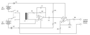
The ELF Sensor enables an experimenter to measure oscillations in the ambient magnetic field occuring at frequencies from a few Hertz up to a few Kilohertz. The ELF Sensor consists of a large inductor which converts variations in the ambient magnetic field into weak electrical signals, and amplifiers which boost these weak electrical signals up to measurable levels. The ELF Sensor is powered by two 9-volt batteries.
The output from the ELF Sensor would normally be connected to a multimeter which is capable of reading AC Volts (the meter should have a scale suitable for measuring weak AC voltages on the order of 100 millivolts RMS). Serious researchers may select multimeters which are also capable of displaying frequencies. This option would enable the researcher to obtain additional information about the source of the magnetic oscillations.
When selecting a multimeter with a Frequency Counter function, one should give special consideration to the meter's frequency response. Many "economy grade" meters will not measure frequencies below 30 or 40 Hertz - this limitation might cause the researcher to lose crucial data. If the researcher's budget will allow it, the Craftsman model 82356 multimeter (available from Sears) is a good choice, measuring frequencies all the way down to one Hertz.
CONSTRUCTING THE ELF SENSOR
The sensor circuit may be conveniently assembled on a perf board and mounted inside a plastic box (do not use a steel box!). The average electronics hobbyist who has experience with soldering should be able to complete the project in one evening. No special construction techniques are necessary, and component placement is not critical. It is recommended that the circuit be built using a socket (eg, Radio Shack # 276-1995) to hold the TL082 amplifier IC - after everything else is complete, the TL082 IC may be plugged into the socket and the ELF Sensor will be ready for operation.
The inductor is a Hammond 158L Filter Choke, available from Antique Electronic Supply, 6221 S. Maple Ave, Tempe AZ 85283 (phone 1-480-820-5411, ask for part number P-T158L). The other components are available from Radio Shack.
Parts List
- L1 - Hammond 158L Filter Choke
- R1 - 4.7 K resistor
- R2 - 1 Meg resistor
- R3 - 100 K resistor
- R4 - 100 K resistor
- R5 - 470 ohm resistor
- R6 - 680 ohm resistor
- D1 - 1N914 diode
- D2 - 1N914 diode
- C1 - 220 pF capacitor
- C2 - 10 uF capacitor, Non-polarized Electrolytic
- U1 - TL082 Op Amp IC
- S1 - DPDT toggle switch
- VR1 - 100 K potentiometer
- Miscellaneous - plastic project box, perf board, battery clips, binding posts, wire, hardware (nuts & bolts)
USING THE ELF SENSOR
The household wiring inside the average home produces a weak 60 Hertz electromagnetic field on the order of one or two milligauss. When VR1 is adjusted for maximum gain and the ELF Sensor is connected to a multimeter, the weak 60 Hertz field should produce a reading of a few hundred millivolts AC. If the meter incorporates a Frequency Counter function, it should display a frequency of 60 Hertz. At times, the electromagnetic fields from household appliances might cause the meter to display a reading of 120 Hertz, or some other harmonic of 60 Hertz.
Along with the 60 Hertz background noise, other weak magnetic disturbances might be present - these pulses may cause the meter to display a frequency slightly higher than 60 Hertz. The capacitor C1 serves to filter out signals above a frequency of one Kilohertz. While this may be useful to obtain a "pure" reading of 60 Hertz, it might also cause the researcher to lose vital data if a higher-frequency magnetic anomaly should occur. Therefore, it is wise to mount the capacitor C1 in a socket, or in some other manner which permits the capacitor to be easily removed.
If the ELF Sensor is used outdoors, the 60 Hertz background noise should not be a problem - the researcher can adjust VR1 to provide any level of gain that he/she desires. However, if the ELF Sensor is used indoors, the researcher may wish to reduce the gain until the meter's frequency counter no longer registers the ambient 60 Hertz background noise. In effect, VR1 may be used as a "squelch control" for the frequency counter. When the gain is set properly, the system will ignore weak magnetic fields on the order of one or two milligauss. If a stronger anomaly should occur, the meter will display its associated frequency.
Another possibility is to connect the ELF Sensor's output to a spectrum analyzer, instead of a multimeter. A spectrum analyzer intended for home stereo equipment provides satisfactory results. When the system gain is properly set, the spectrum analyzer will display the 60 Hertz background noise. If a magnetic anomaly should suddenly occur, its strength and frequency can be readily observed on the spectrum analyzer's display.
Web Page created by Dr. Dave Oester, Webmaster
Copyrighted ® 2000 by Dave Oester, All Rights Reserved